Toll Free: 1800 3000 6222
Telephone: +91 141 222 3221
Fax: +91 141 222 1926, 222 2259
CIN: U29130WB1946PLC013643
Founded in 1946, National Engineering Industries Ltd (NEI) is India’s leading bearings manufacturer and exporter, renowned for excellence in quality and delivery.

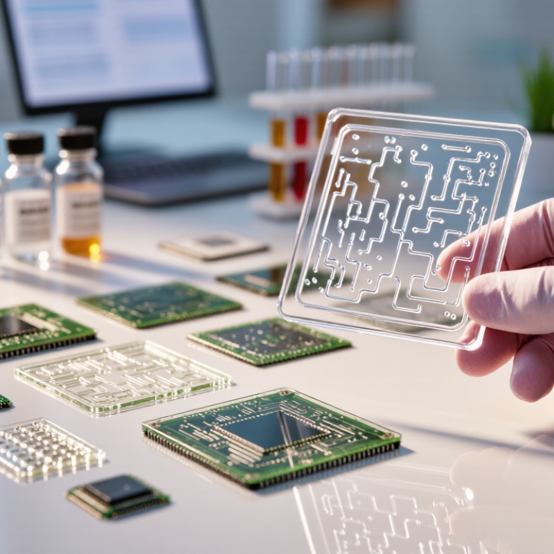
Choosing the right Microfluidic Chips is not a simple matter of selecting the smallest channels. It requires matching chip design with the sample, workflow, instrument, and final measurement. A chip that handles clear buffer perfectly may clog when exposed to whole blood, viscous proteins, or cell-rich samples. The decision begins with practical questions: What volume must be processed? How much pressure is available? Will the device require optical access, temperature control, or electrical sensing?
George M. Whitesides, a leading Harvard chemist and microfluidics researcher, described the field this way: “Microfluidics is the science and technology of systems that process or manipulate small amounts of fluids, using channels with dimensions of tens to hundreds of micrometres.” That definition highlights the central challenge. Tiny dimensions create precise control, but they also magnify surface effects, air bubbles, contamination, and manufacturing variation. Small errors become visible.
A reliable selection process should compare materials, channel geometry, flow control, chemical compatibility, and production quality. Glass offers strong optical clarity and chemical resistance. Polymer chips may reduce cost and support rapid prototyping. Yet, neither option is automatically better. It depends on the application.
Testing matters more than attractive specifications. Run the intended sample through a prototype. Watch for bubbles at the inlet, residue near turns, and unstable flow after repeated use. Some published performance claims also need careful verification. They may not reflect real laboratory conditions.
The right Microfluidic Chips should support dependable results, not merely impressive engineering. There will be compromises. That is normal. A thoughtful choice makes those compromises visible before they become expensive failures.
Microfluidic chip selection begins with basic flow behavior. A chip guides tiny liquid volumes through designed channels. These channels may include inlets, mixers, valves, filters, and detection zones. In practical testing, channel width, depth, and surface chemistry strongly affect performance. A narrow channel can improve control but may increase clogging risks. Material choice also matters. Glass supports optical clarity, while polymers may offer easier fabrication. Small details matter.
Core designs serve different experimental goals. Continuous-flow chips suit steady mixing, cell handling, and chemical reactions. Droplet chips divide liquids into uniform microreactors. Digital microfluidic platforms move droplets across patterned electrodes. Paper-based designs support simple, low-resource testing.
I have learned that an elegant design can still fail under real pressure changes. Temperature, sample viscosity, and air bubbles often behave differently than expected. This is why reliable selection requires published specifications, repeatability tests, and direct compatibility checks.
Define the sample type before choosing a chip. Measure viscosity, required volume, and target flow rate. Check whether the chip supports your detection method. Test with safe reference fluids first. Record pressure, temperature, and visible bubble formation. A short pilot run can reveal problems early.
Choose a microfluidic chip by defining the experiment before comparing channel designs. What decision must the experiment support? Are you measuring cell behavior, mixing speed, particle separation, or reagent consumption? Translate that purpose into measurable requirements, including sample volume, flow rate, pressure range, temperature, detection method, and acceptable variability.
In my laboratory planning, unclear goals often create expensive compromises. A chip may offer excellent mixing but produce excessive dead volume. Another may support high pressure but damage fragile cells. Specify the minimum sample volume, target throughput, assay duration, and recovery rate. Include material compatibility and optical clarity when imaging matters. A 2024 industry assessment estimated the global microfluidics market at roughly USD 28 billion in 2023, with double-digit growth expected through 2030. Grand View Research, Microfluidics Market Size Report, 2024. This growth reflects broad adoption, not universal chip suitability. Market data can guide attention, but it cannot replace validation.
Tips: Build a short requirements table before contacting suppliers. Mark each item as essential, preferred, or unknown. Test the real sample early, because buffer performance can mislead you. Keep one imperfect trial. It may reveal the hidden constraint. Record pressure changes, bubbles, clogging, and time-to-result. These details frequently determine whether a chip works outside ideal conditions. A pilot comparison with two designs is often more informative than a long specification sheet.
Chip material determines whether an experiment remains stable or quietly fails. Glass offers strong chemical resistance and a smooth surface for imaging. It suits organic solvents, aggressive buffers, and long-term optical monitoring. Polydimethylsiloxane is easy to prototype, but it can absorb small hydrophobic molecules. That weakness may distort drug-response results. Cyclic olefin polymers provide low autofluorescence and limited water absorption. They often fit disposable assays and sensitive fluorescence work. Silicon handles heat well, yet its opacity limits direct observation.
Material selection should follow the sample, not only the chip price. A 2023 MarketsandMarkets report valued the global microfluidics market at USD 28.2 billion and forecast USD 58.8 billion by 2028. This growth increases material choices, but not decision quality.
Tips:
Build a compatibility table before ordering. Test the exact solvent, concentration, temperature, and exposure time. A short soak test can reveal swelling, leakage, or optical changes. For cells, check surface charge, protein adsorption, and shear stress. Primary cells may react differently from immortalized lines.
I still test the wrong material sometimes. That mistake is useful, but expensive. Also inspect sample viscosity and particle content. Whole blood, mucus, and tissue suspensions can clog narrow channels. A wider inlet may protect the experiment better than a smaller channel. The NIST Microfluidics in Biomedical Research report emphasizes standardized testing for flow, materials, and assay reproducibility. Treat its message seriously: a chip is part of the method, not just a container.
Choosing the right microfluidic chip starts with channel architecture, not price. A 50–100 micrometer channel can support rapid transport, but it may clog when samples contain cells or particles. Wider inlets, rounded corners, and short dead-end sections reduce this risk. In practice, inspect the chip under a microscope before testing. Tiny bubbles often reveal poor priming or unsuitable geometry. Grand View Research valued the global microfluidics market at approximately US$29 billion in 2023, showing how quickly these design decisions affect a growing field.
Flow control determines repeatability. Pressure-driven systems usually provide steadier flow than manual syringes, especially below 10 microliters per minute. However, tubing compliance can delay changes and create unwanted pressure pulses. Add a bubble trap, measure resistance, and record the actual flow rate at the outlet. A 2023 review in Lab on a Chip noted that flow instability remains a major barrier to reliable point-of-care microfluidic testing. The lesson is practical: calculated flow is not measured flow.
Detection methods should match the channel and the question. Optical detection suits transparent chips and enables real-time imaging, while electrochemical sensing can reduce instrument size. Check optical path length, background fluorescence, electrode placement, and signal-to-noise performance. The analytical method may be sensitive, but sensitivity alone is not enough. Some published demonstrations use ideal samples, not viscous clinical matrices. That gap deserves attention. Choose chips tested with representative samples, documented controls, and calibration data.
| Chip Architecture | Channel Structure | Flow Control Options | Compatible Detection Methods | Typical Dimensions | Key Advantages | Best-Fit Applications | |
|---|---|---|---|---|---|---|---|
| Straight Parallel Channels | One or more linear channels with uniform cross-sections. Multiple lanes can be used for parallel testing or reference controls. | Pressure-driven pumps, syringe pumps, peristaltic pumps, or gravity-driven flow. Passive resistance can balance parallel lanes. | Bright-field imaging, fluorescence microscopy, absorbance, impedance, and electrochemical sensors placed along the channel. | Common channel widths are approximately 50–500 µm; heights are often 20–200 µm, depending on the assay and sample type. | Simple layout Easy modeling Low fabrication risk Good for observing transport, cell behavior, and reaction progress under steady flow. | Limited mixing without added structures. Flow distribution may become uneven if inlet resistance or channel dimensions vary. | Cell culture, diffusion studies, reaction monitoring, and basic analytical assays. |
| Serpentine or Herringbone Mixer | Repeated bends, turns, grooves, or ridges increase interface deformation and generate secondary flows. | Two or more inlet streams controlled by pressure or syringe pumps. Flow-rate ratio determines mixing time and concentration. | Fluorescence intensity, absorbance, Raman or infrared methods, and microscopy-based reaction monitoring. | Channel widths commonly range from about 50–300 µm; mixing sections may extend from a few millimeters to several centimeters. | Fast passive mixing No moving parts Improved mixing at low to moderate Reynolds numbers compared with a straight channel. | Higher pressure drop than a straight channel. Surface grooves may increase fouling or complicate cleaning. | Buffer exchange, reagent mixing, nanoparticle synthesis, enzyme reactions, and dilution series. |
| Droplet or Flow-Focusing Chip | A dispersed phase is pinched by a continuous phase through a T-junction, flow-focusing junction, or similar geometry. | Independently controlled pressure or syringe-pump lines for the dispersed and continuous phases. Droplet size depends on flow-rate ratio, viscosity, interfacial tension, and junction geometry. | Bright-field and fluorescence imaging, droplet fluorescence intensity, absorbance, Raman methods, and electrical impedance. | Junction widths are frequently about 20–200 µm; droplet diameters are often approximately 20–300 µm, depending on the design. | Compartmentalization Low reagent use High-throughput generation of isolated reaction volumes with narrow size distributions under stable conditions. | Sensitive to surfactant selection, wettability, pressure stability, and particles or aggregates in the sample. | Digital assays, single-cell analysis, directed evolution, biochemical screening, and emulsion-based synthesis. |
| Gradient Generator | A network of split-and-recombine branches creates spatial or outlet-to-outlet concentration gradients. | Pressure-driven or syringe-pump flow through two or more inlets. Hydraulic resistance determines the mixing and splitting ratios. | Fluorescence imaging, absorbance mapping, luminescence, electrochemical readout, and microscopy of exposed cells or materials. | Branch channels are commonly 50–300 µm wide, with several repeated network stages used to improve gradient uniformity. | Parallel concentrations Reduced manual dilution Enables dose-response testing and spatial exposure studies from a small number of input solutions. | Gradient accuracy depends on resistance matching, diffusion time, inlet stability, and consistent channel fabrication. | Drug screening, chemotaxis, toxicity testing, cell differentiation, and material response studies. |
| Membrane-Separated Chip | Two fluidic chambers are separated by a porous membrane or thin barrier for transport, coculture, or selective exchange. | Independent pumps or pressure controllers for each chamber. Flow rates should be balanced to avoid excessive membrane deformation or leakage. | Fluorescence microscopy, permeability measurements, transepithelial electrical resistance, impedance, and endpoint staining. | Chamber heights are often about 50–500 µm; membrane thickness and pore size vary widely with the biological or separation objective. | Compartmental control Selective transport Supports barrier models, coculture, diffusion testing, and separation processes. | Membranes can foul, absorb analytes, tear, or introduce additional transport resistance. Optical access may be reduced. | Organ-on-chip models, permeability assays, cell coculture, filtration, and mass-transfer studies. |
| Valve-Integrated Network | Intersecting flow and control layers use pneumatic or mechanical valves to route, isolate, meter, or multiplex fluids. | External pressure regulators, solenoid valves, vacuum systems, or integrated pneumatic control lines. Valve timing controls fluid routing. | Fluorescence, chemiluminescence, absorbance, electrical impedance, electrochemical sensing, and integrated optical readout. | Analytical channels commonly range from about 20–200 µm in height; control-layer geometry depends on valve type and membrane thickness. | Automated routing Low dead volume Enables sequential protocols, reagent metering, sample isolation, and high experimental repeatability. | More complex fabrication and instrumentation. Valve materials may swell, fatigue, or interact with organic solvents. | Automated sample preparation, multiplexed assays, cell sorting workflows, and programmable biochemical protocols. |
| Digital Microfluidic Electrowetting | Discrete droplets move across a patterned electrode array, usually on a hydrophobic dielectric surface rather than through enclosed channels. | Electrical actuation changes the contact angle and moves droplets by electrowetting. Droplet routing is controlled by electrode sequence and voltage. | Optical imaging, fluorescence, absorbance, electrochemical sensing, and thermal measurements. | Droplet volumes commonly range from nanoliters to microliters; electrode pitch is often approximately 0.5–5 mm. | Reconfigurable Low dead volume Flexible routing, mixing, splitting, and dispensing without a permanently fixed channel network. | Requires electrical control hardware. Performance can be affected by surface contamination, dielectric defects, evaporation, and electrowetting hysteresis. | Automated sample preparation, clinical test workflows, biochemical assays, and portable analytical systems. |
| Paper or Porous-Membrane Microfluidics | Patterned porous media transport liquid through capillary action, wicking, or localized barriers. | Primarily passive capillary flow. Flow can be adjusted through pore structure, paper thickness, barriers, added reagents, or external compression. | Colorimetric, fluorescence, chemiluminescence, electrochemical, and smartphone-assisted image analysis. | Patterned paths are often about 0.5–3 mm wide; porous layers may range from tens to several hundred micrometers thick. | Low cost No pump required Lightweight, disposable, and suitable for decentralized testing with small sample volumes. | Limited control of flow rate and timing. Variable wetting, evaporation, matrix effects, and lower precision can affect quantitative performance. | Point-of-care testing, environmental screening, education, and rapid qualitative or semi-quantitative assays. |

Note: Dimensions and operating ranges are representative design ranges rather than fixed specifications. Final chip selection should also consider material compatibility, surface treatment, sample viscosity, required throughput, sterility, optical path length, and the available pumping and detection equipment.
How to Choose the Right Microfluidic Chips?
Manufacturing options shape chip performance, price, and delivery time. Glass offers strong chemical resistance and clear optical inspection. Polymers usually reduce production costs and support rapid prototyping. Elastomers can work well for flexible valves, but they may absorb certain compounds. I have seen promising designs fail because the material changed the sample. Material choice is rarely a small detail.
Check compatibility with solvents, temperature, pressure, tubing, and detection equipment. Confirm channel dimensions and connector standards before ordering samples. A chip that fits the microscope may still require expensive pumps or custom holders. Ask for measured tolerances, surface treatment details, and leak-test data. Claims without test conditions deserve caution.
Cost needs a wider view. Include tooling, setup, shipping, consumables, labor, and failed runs. A cheap prototype can become expensive at higher volumes. Manufacturing scalability also matters. Compare manual assembly, small-batch molding, and automated production. Request sample units from a realistic production process, not only laboratory prototypes. My earlier estimates sometimes ignored packaging and inspection time. That was a useful mistake.
Tips: Build a simple comparison table. Score compatibility, repeatability, lead time, and waste. Test the most chemically demanding sample first. Keep two manufacturing routes under review. Small design changes can improve yield dramatically. Don’t optimize price too early.
Copyright © 2023 NEI Ltd. All rights reserved.
Registered Office : 9/1, R. N. Mukherjee Road, Kolkata – 700 001. In case of any queries or grievances, please contact Mr.Tarun Kumar Kabra, Company Secretary.
E-mail: sale@kinpart.com Privacy Policy Cookie Policy