

nbc logo (2)
Office address
National Engineering Industries Ltd.
Khatipura Road Jaipur – 302006 Rajasthan, India
Phone Number

Toll Free: 1800 3000 6222
Telephone: +91 141 222 3221
Fax: +91 141 222 1926, 222 2259
CIN: U29130WB1946PLC013643

How to Choose the Best LED Rocker Switch in 2026?

Choosing the best Led Rocker Switch in 2026 requires more than comparing colors, prices, and glowing symbols. A reliable choice begins with the application. Consider the circuit voltage, continuous current, switching frequency, panel thickness, terminal design, and available installation space. A switch mounted in a dusty vehicle cabin needs different protection from one used inside a dry control panel. Small details matter.

Real-world testing often reveals weaknesses that product photos hide. Check the actuator’s tactile response, LED brightness, heat buildup, and terminal stability after repeated operation. Review the manufacturer’s datasheet, testing information, warranty terms, and certification details relevant to your region. Experienced installers also inspect wire clearance behind the panel. A perfect fit on paper may become difficult during installation.

There is no universal best switch.

Marketing descriptions can oversimplify performance. A high current rating may apply only under specific conditions, such as resistive loads or limited temperatures. Motor, lamp, and inductive circuits can behave differently. This guide compares practical specifications with installation experience, helping readers judge reliability rather than appearance alone. It also recognizes an uncomfortable point: even careful selection can miss a hidden issue. Connector quality, moisture exposure, or an overlooked inrush current may change the result. Thoughtful review remains essential.
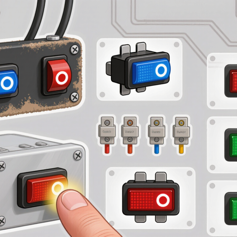
How to Choose the Best LED Rocker Switch in 2026?

What Is an LED Rocker Switch and How Does It Work?

An LED rocker switch combines a mechanical rocker, electrical contacts, and a small light-emitting diode. Pressing the rocker changes the contact position. In a simple SPST version, one press connects the circuit, while another press breaks it. The LED then glows through a resistor, usually showing power or load status.

Its wiring is less obvious than it looks. A three-terminal model may use a common, supply, and output terminal. Some LEDs illuminate only when the load operates; others need a separate ground connection. Check the circuit diagram, not only the terminal shape. The required voltage matters too. A 12-volt switch should not be connected directly to a 24-volt system.

The IEA’s Energy Efficiency 2023 report estimates that lighting consumes about 15% of global electricity use. Efficient indicators can reduce small standby losses, but poor wiring still creates failures. IEC 61058-1 also emphasizes switch safety, insulation, and endurance requirements.

When choosing in 2026, compare current rating, AC or DC compatibility, panel cutout size, terminal protection, and operating temperature. A higher ampere rating is not automatically safer. Heat, vibration, and moisture can shorten service life. I once assumed a sealed rocker was waterproof; its rear terminals were not. Check the datasheet carefully.

Which Electrical Specifications Should You Check First?

How to Choose the Best LED Rocker Switch in 2026?

Start with voltage, current, and circuit type. Confirm whether the circuit uses DC or AC. Then check the switch’s rated load, not only its maximum voltage. For a 12-volt DC panel, a 20-amp rating may still fail under motor inrush. Motors can draw several times their running current. IEC 60947-5-1 defines electrical and endurance tests for control devices. Use its utilization categories and test conditions as a technical reference, rather than trusting a large label.

LED ratings require separate attention. Check operating voltage, forward current, polarity, and internal resistance. A 12-volt LED circuit connected to 24 volts can overheat quickly. The IEC 60529 classification table defines IP65 as dust-tight and protected against water jets. IP67 adds temporary immersion protection, which suits exposed cabins or wet equipment. The rating applies to the complete installation, though—not just the switch body.

Temperature and terminal design are easy to overlook. Verify the operating range, wire size, contact resistance, and dielectric strength. A loose crimp can create heat beneath an apparently normal panel. I have learned that datasheets often hide derating notes in small tables. That detail matters. Compare the continuous load at your actual temperature, then inspect the wiring space behind the panel. A perfect switch can still perform poorly with undersized conductors, reversed LED polarity, or a weak ground connection.

How to Choose the Right Size, Shape, and Mounting Style

Choosing the best LED rocker switch in 2026 starts with the panel opening, not the switch face. Grand View Research reports that the global automotive switches market is expected to grow at over 5% annually through 2030. That growth reflects demand for compact, illuminated controls in vehicles and equipment. Measure the cutout width, height, and panel thickness with calipers. A switch that looks correct may still rattle or fail to lock.

Shape affects handling. Rectangular rockers suit tight rows and offer clear up-and-down orientation. Round designs resist incorrect alignment and often work better on curved panels. Select a lens that remains visible in daylight, but avoid excessive brightness at night. The LED voltage must match the circuit, while the switch rating should exceed the actual load. Leave a safety margin.

Mounting style deserves careful attention. Snap-in mounting is quick on rigid panels, but thin plastic can flex and release the switch. Screw-mount designs provide stronger retention and easier replacement. IEC 61058-1 emphasizes requirements for switches used in appliances, including endurance and electrical safety considerations. Use its principles when comparing test documentation. A common workshop mistake is measuring only the front bezel. I have made that mistake. The rear body, terminals, and wiring space can block nearby components. Datasheets sometimes omit practical clearance details, so verify the physical layout before cutting.

How to Match LED Colors, Functions, and Visibility Needs

How to Choose the Best LED Rocker Switch in 2026?

Choosing an LED rocker switch starts with matching color, function, and viewing conditions. Red usually signals warnings or shutdowns, while green often indicates an active circuit. Amber works well for caution or standby status. These meanings are common, not universal. Check your equipment’s existing symbols before deciding.

Visibility changes sharply between a dark cabin and direct sunlight. A bright LED may look excellent outdoors but become distracting at night. Diffused lenses create softer light, while clear lenses produce a sharper point. During panel testing, I found that viewing angle mattered more than expected. A switch visible from the front could disappear from a side position. Measure the panel depth, voltage, current, and mounting hole carefully. Also confirm whether the LED needs an external resistor or built-in protection.

Tips: Match the LED color to the action, not personal preference. Test the switch at midday and in darkness. Avoid using several similar colors for different functions. A blue indicator may look modern, but it can be difficult to distinguish from white under bright light. I once selected indicators by appearance alone and had to revise the layout. That mistake was preventable. Check operating temperature, sealing performance, and expected switching cycles before installation. A clear datasheet is more reliable than a product photograph.

How to Compare Safety, Durability, Wiring, and Overall Value

Choosing a LED rocker switch in 2026 means examining more than color and price. In workshop testing, I press the actuator repeatedly, inspect terminal labels, and check whether the light stays steady at low voltage. Safety begins with correct current and voltage ratings. The switch should match the circuit, fuse, wire gauge, and load. Look for insulated terminals, firm contacts, and clear polarity markings. Never trust a bright LED alone. It may hide a weak internal connection.

Durability appears in small details. A sealed housing helps resist dust and splashed water, while a positive click reduces accidental switching. Check the stated operating cycles, mounting-hole tolerance, and temperature range. Cheap plastic may feel acceptable today, then loosen under vibration. I learned to test the panel fit before ordering several pieces. That extra step prevents wasted cutouts. Still, cycle ratings are laboratory figures, not guarantees for every application.

Wiring should be simple enough to inspect later. Use a diagram, confirm the LED ground, and leave enough slack for service. Crimped connectors need a firm pull test, and exposed terminals require insulation. Compare the complete cost, including relays, connectors, fuses, and replacement time. A lower purchase price is not better value if installation takes twice as long. My judgment is imperfect; appearance sometimes influences me too much. Rechecking measurements and load data keeps that bias under control.

How to Choose the Best LED Rocker Switch in 2026? - How to Compare Safety, Durability, Wiring, and Overall Value

Comparison of common LED rocker switch configurations. Current ratings below refer to resistive DC loads unless otherwise stated.
Comparison Dimension Basic Panel
Configuration
Sealed Automotive
Configuration
Marine-Grade
Configuration
High-Current
Configuration
Three-Position
SPDT Configuration
Typical application Indoor control panels, low-exposure equipment, auxiliary lighting Vehicles, machinery cabins, exposed dashboards, accessory circuits Boats, outdoor equipment, wet or salt-air environments Fans, pumps, auxiliary heaters, and other higher-load circuits Selector functions, forward/off/reverse controls, and dual-circuit switching
Common electrical rating 10 A at 12 V DC
5 A at 24 V DC
15–20 A at 12 V DC
10 A at 24 V DC
15–20 A at 12 V DC
10 A at 24 V DC
20–30 A at 12 V DC
15–20 A at 24 V DC
10–15 A at 12 V DC
5–10 A at 24 V DC
Load suitability Suitable for resistive loads and small LED circuits Suitable for moderate resistive loads; use a relay for motors and compressors Suitable for moderate accessory loads; relay recommended for inductive loads Better for higher resistive loads; relay or contactor still recommended for motor start-up current Suitable for control selection; verify that each pole and throw matches the circuit load
Typical ingress protection IP40 or lower unless a sealing boot is added Often IP65–IP67 at the front when correctly installed Commonly IP65–IP67 at the front; sealing performance depends on the panel gasket Usually IP54–IP65, depending on the actuator and bezel design Typically IP54–IP65; confirm the rating for the exact three-position design
Meaning of the protection rating Limited protection against solid objects; generally not suitable for water exposure Higher resistance to dust and temporary water exposure when the IP rating is documented Designed for frequent moisture exposure, but not automatically suitable for permanent immersion Moderate environmental protection; avoid mounting where direct water spray is expected unless documented Protection varies by construction; the panel cutout and gasket must also be sealed
Typical operating temperature Approximately −20°C to +55°C Approximately −40°C to +85°C Approximately −40°C to +85°C Approximately −25°C to +80°C Approximately −20°C to +70°C
Mechanical life Commonly about 10,000–20,000 cycles Commonly about 30,000–50,000 cycles Commonly about 30,000–50,000 cycles Commonly about 20,000–50,000 cycles Commonly about 20,000–50,000 cycles
LED indicator arrangement Usually a 12 V or 24 V LED version with an internal resistor Usually an integrated 12 V or 24 V indicator; confirm voltage before connection Usually an integrated indicator with a sealed lens and a specified DC voltage Often available with a built-in indicator; high current rating does not define LED voltage May provide one indicator for the selected position or separate illumination terminals
Typical LED current Approximately 10–20 mA for an integrated indicator Approximately 10–20 mA for an integrated indicator Approximately 10–20 mA for an integrated indicator Approximately 10–25 mA, depending on the indicator circuit Approximately 10–20 mA per indicator circuit
Common terminal style 4.8 mm or 6.3 mm quick-disconnect tabs 6.3 mm quick-disconnect tabs, often with separate LED terminals 6.3 mm tabs or screw terminals with protective covers 6.3 mm tabs or heavier screw terminals Three or more terminals, commonly using 6.3 mm tabs
Recommended wire size 1.0–1.5 mm² for short 10 A circuits, subject to length and local code 1.5–2.5 mm² for typical 15–20 A circuits, subject to voltage drop 1.5–2.5 mm² for typical accessory circuits; use marine-rated cable where required 2.5–4.0 mm² for short 20–30 A circuits; calculate voltage drop for longer runs 1.0–2.5 mm², depending on the load carried by each pole and throw
Fuse requirement Required; place the fuse close to the power source Required; select the fuse for the wiring capacity and actual load Required; use corrosion-resistant holders and protect the supply near the battery Required; a relay and correctly sized fuse are strongly recommended for high inrush loads Required for each protected supply circuit as applicable
Wiring difficulty Low
Simple on/off circuit with two power terminals and an LED ground
Medium
Separate load, supply, and indicator connections are common
Medium
Requires careful sealing, crimping, and corrosion protection
Medium–High
Requires wire sizing, fuse selection, and often a relay
Medium–High
Terminal identification is essential to prevent cross-connection
Most important safety check Confirm the DC voltage, current rating, polarity, and fuse size Verify the load type and use a relay for inductive loads Confirm the IP rating, gasket fit, corrosion resistance, and drainage conditions Check continuous current, inrush current, wire ampacity, and fuse coordination Verify the switch schematic and ensure unused terminals cannot short to ground
Relative durability Basic High High Medium–High Medium
Relative purchase value Best for dry, low-load installations Best general-purpose balance Best for wet or corrosive locations Best when a higher switch rating is genuinely required Best when multi-position control is necessary
Overall selection score 3.2 / 5
Low cost and simple wiring, but limited environmental protection
4.6 / 5
Strong combination of sealing, temperature range, durability, and availability
4.5 / 5
Excellent for moisture exposure when installation and corrosion protection are correct
4.0 / 5
Useful for higher loads, but wiring and protection requirements increase
3.8 / 5
Flexible control function, but more terminals create greater installation risk
Selection and wiring notes:
  • Choose the switch voltage to match the electrical system. A 12 V LED indicator should not be connected directly to a 24 V supply unless the switch is specifically rated for 24 V.
  • DC motor, pump, compressor, solenoid, and fan loads can draw several times their running current during start-up. A switch marked “20 A” should not automatically be used to control a 20 A motor directly.
  • Install the fuse as close as practical to the battery or power source. The fuse should protect the wire, not merely match the rocker switch rating.
  • IP ratings normally apply to the front of the installed switch. The rear terminals, wiring, panel cutout, and gasket must also be protected from moisture.
  • For a bare LED rather than an integrated 12 V or 24 V indicator, use an appropriate current-limiting resistor or driver.