nbc logo (2)
Office address
National Engineering Industries Ltd.
Khatipura Road Jaipur – 302006 Rajasthan, India
Phone Number

Toll Free: 1800 3000 6222
Telephone: +91 141 222 3221
Fax: +91 141 222 1926, 222 2259
CIN: U29130WB1946PLC013643

How to Choose a Peripheral Driving Thickener in 2026?

Choosing a Peripheral Driving Thickener in 2026 requires more than comparing tank diameter, torque, or supplier reputation. The decision affects water recovery, underflow density, power use, maintenance access, and plant stability. The World Bank’s 2023 water report highlights continuing pressure on industrial water efficiency, while the International Energy Agency reports that minerals processing remains energy-intensive. These trends make thickener performance a practical cost issue, not merely a design preference.

Mineral-processing specialist Dr. Alan L. Mular once warned, “Thickening is a test of process understanding, not simply equipment selection.” His point remains useful. A peripheral drive may suit large-diameter tanks, heavy rake loads, and accessible maintenance layouts, but only when feed chemistry and settling behaviour support it. Operators should examine flocculant demand, bed compression, rake torque, overflow clarity, underflow yield stress, and seasonal ore changes. A small pilot test can reveal more than a polished brochure. It can also expose uncomfortable assumptions.

Recent technical guidance from Metso and FLSmidth stresses process testing, instrumentation, and reliable torque protection in modern thickener systems. Yet no report can perfectly predict every site. Clay content may shift. Feed density may drift. A design that works in a laboratory can struggle beside a dusty, vibrating plant. This guide explains how to compare Peripheral Driving Thickener options using measurable evidence, lifecycle cost, service capability, and realistic operating risks. The best choice is rarely the largest machine. It is the one that keeps water clear, torque controlled, and operators confident.

How to Choose a Peripheral Driving Thickener in 2026?

What Is a Peripheral Driving Thickener and How Does It Work?

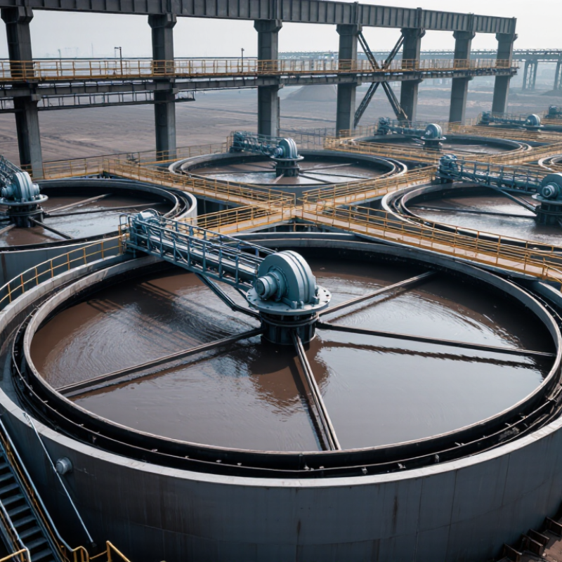
A peripheral driving thickener is a circular tank that concentrates suspended solids before digestion, dewatering, or disposal. Its drive unit sits near the tank wall and moves a rotating bridge around the perimeter. Scraper arms then travel slowly across the floor. Settled solids move toward a central hopper, while clarified liquid exits through an overflow weir.

The process looks simple, but torque matters. As sludge thickens, resistance can rise sharply near the hopper. A properly sized drive maintains steady movement without excessive rake stress. Feed enters near the center, allowing solids to settle through a calmer zone. Surface skimmers remove floating material. Thickened sludge leaves through an adjustable withdrawal line.

The U.S. EPA’s 2022 Clean Watersheds Needs Survey estimated $630.1 billion in documented wastewater infrastructure needs. That figure highlights why reliable solids handling deserves early attention. WEF Manual of Practice No. 8 also treats solids loading, hydraulic loading, scraper design, and operational control as connected decisions. Still, published capacity tables cannot replace site testing. Sludge characteristics change with season, industry, rainfall, and biological treatment. A larger drive is not automatically safer. It may increase cost without solving poor feed distribution. The common mistake is selecting diameter first and checking torque later. Water temperature, grit, corrosion, standby requirements, and operator access need equal scrutiny. Some designs look efficient on paper. Field conditions can disagree.

How to Choose a Peripheral Driving Thickener in 2026?

What Is a Peripheral Driving Thickener and How Does It Work?

A peripheral driving thickener is a circular sedimentation tank in which a drive mechanism travels around the tank perimeter while rotating scraper arms collect settled solids toward a central underflow outlet. The chart shows the estimated daily solids-handling capacity for representative tank diameters, calculated at a design solids flux of 80 kg/m²·day. Larger diameters provide more settling area, but final selection must also consider feed solids concentration, settling tests, hydraulic loading, rake torque, underflow density, climate, and site constraints.

Capacity values are calculated from tank area × 80 kg/m²·day and are intended for preliminary comparison rather than final equipment sizing.

Which Industrial Requirements Should Guide Your Equipment Selection?

Selecting a peripheral driving thickener in 2026 should begin with process requirements, not catalog dimensions. Define daily throughput, feed solids, particle size, settling rate, and target underflow density. A laboratory settling test can reveal problems that a standard datasheet may hide. Small differences in mineral behavior can change torque demand significantly.

Site conditions also guide the equipment choice. Check tank diameter, available headroom, foundation strength, ambient temperature, and access for maintenance. A unit may perform well in a test area but fail when winter temperatures increase sludge resistance. Consider corrosion exposure, wash-water availability, electrical supply, and control-system compatibility. Keep critical measurements documented.

Drive selection deserves careful attention. Estimate peak torque, continuous torque, rake speed, and overload response from actual operating data. Do not size only for average conditions. A conservative design may reduce stoppages, but excessive capacity can increase cost and energy use. Bigger is not automatically safer.

Operators should also review scraper lifting, emergency stopping, instrumentation, and spare-part access. Ask how the mechanism behaves during feed surges or uneven settling. No calculation is perfect. Field data should challenge the original assumptions. A clear commissioning plan, operator training, and routine torque trending improve reliability after installation. If the process changes later, the selected equipment may need more flexibility than today’s production target suggests.

How to Compare Thickener Design, Capacity, and Operating Performance?

How to Choose a Peripheral Driving Thickener in 2026?

A peripheral driving thickener should be compared through design, capacity, and operating performance. Do not judge it by tank diameter alone. Examine the feedwell, rake structure, drive system, and sludge discharge arrangement. A well-designed feedwell reduces turbulence and improves settling across changing feed conditions. The rake must move settled solids without excessive torque or lifting. Check torque protection, rake-lift response, and access for inspection. These details matter during cold starts and uneven loading.

Tips: Request test data using representative slurry. Compare overflow clarity, underflow density, torque trends, and flocculant demand. Ask for performance figures at both normal and peak feed rates. Check whether the quoted capacity includes realistic solids concentration, not only hydraulic flow. Small wording differences can hide large operating risks.

Capacity should cover flow, solids loading, retention time, and available settling area. Operating performance is more practical than a catalogue number. Review daily underflow density, overflow suspended solids, power use, and control stability. A thickener that reaches high density but frequently trips may create more cost than value. Ask how operators respond to rising torque, changing mineralogy, or short-term feed surges. Field experience shows that maintenance access often influences uptime more than expected. Still, predictions remain imperfect. Site testing and conservative design assumptions are worth the extra effort.

What Materials, Controls, and Maintenance Features Should You Evaluate?

A peripheral driving thickener should be evaluated as a working system, not merely as a circular tank. Start with the feed chemistry, solids concentration, temperature, and expected torque. Carbon steel with a suitable coating may reduce capital cost, while stainless steel or composite components can better resist chlorides and abrasive sludge. Material compatibility matters most around the rake arms, scraper blades, fasteners, and feedwell.

Control features deserve equal attention. Specify variable-speed drive control, torque monitoring, bed-level measurement, automatic rake lifting, and alarms for overload or abnormal torque. A local manual mode is still valuable during sensor failure. It is less sophisticated, but operators can recover faster. The U.S. Department of Energy’s Industrial Motor Systems Market Opportunities Assessment reports that motor-driven equipment accounts for about 23% of U.S. electricity consumption, so efficient drive selection affects long-term operating cost. Oversizing the motor can also create poor low-load efficiency.

Maintenance details often decide availability. Request accessible gearbox inspection points, replaceable seals, corrosion-resistant fasteners, grease schedules, and documented calibration procedures. Keep critical spare parts on site, especially scraper hardware and sensor assemblies. The U.S. EPA’s 2022 Clean Watersheds Needs Survey estimates $630.1 billion in wastewater infrastructure needs over twenty years, reinforcing the value of maintainable equipment. However, published lifecycle figures may not match your sludge. Pilot testing and operator interviews should challenge the specification. That uncomfortable step is often where the best decision begins.

How to Choose a Peripheral Driving Thickener in 2026? - What Materials, Controls, and Maintenance Features Should You Evaluate?

Evaluation Dimension What to Evaluate Practical Data and Selection Benchmarks Recommended Verification Method
Process Duty and Feed Characteristics Confirm the slurry type, solids concentration, particle-size distribution, mineralogy, settling behavior, temperature, pH, and corrosive constituents. Define the design case using normal, minimum, maximum, and upset feed conditions. Record feed solids by mass, slurry density, flow rate, particle-size distribution, and overflow clarity target. Use representative laboratory settling tests, hydraulic calculations, and pilot-scale thickening tests rather than relying only on nominal feed-flow data.
Thickener Diameter and Capacity Assess the required settling area, solids loading rate, hydraulic loading, and available installation space. Size the unit from tested settling performance. Typical industrial units may range from several metres to more than 100 m in diameter, depending on duty and site requirements. Avoid selecting by tank volume alone. Compare the supplier's design basis with measured test results and confirm capacity at the highest expected solids loading and flow rate.
Tank and Launder Materials Evaluate structural steel, concrete, stainless steel, polymer linings, rubber linings, and corrosion-resistant coatings. Carbon steel is commonly used for structural components when protected by a suitable coating. Stainless steel or lined surfaces may be justified for acidic, chloride-bearing, abrasive, or chemically aggressive service. Review slurry chemistry, chloride level, abrasion potential, coating compatibility, design corrosion allowance, and inspection access.
Rake and Scraper Materials Check the construction and wear resistance of rake arms, scraper blades, feedwell components, and mud-zone parts. Common choices include coated carbon steel, stainless steel, abrasion-resistant steel, polyurethane, and replaceable rubber or polymer blades. The selection should reflect particle hardness, underflow density, and expected torque. Request wear-life assumptions, replaceable-component drawings, and compatibility information for abrasive or corrosive slurry.
Feedwell Design Evaluate feed dilution, energy dissipation, flocculant mixing, inlet velocity, and short-circuiting control. A well-designed feedwell should distribute flow evenly, reduce turbulence, and allow flocs to form without excessive shear. Feedwell access should permit inspection and cleaning. Review computational or physical flow studies where appropriate, and confirm expected overflow clarity and settling-zone behavior during testing.
Flocculant and Reagent System Assess polymer preparation, dilution, aging time, dosing accuracy, injection location, and mixing intensity. The optimum polymer dose is application-specific. The system should support controlled dilution and stable dosing over the normal operating range, with provisions for low-flow alarms and flushing. Carry out jar tests or laboratory flocculation tests using actual process water and slurry. Verify polymer consumption per tonne of dry solids.
Drive and Torque Capacity Evaluate the peripheral drive arrangement, gearbox, pinion and ring gear, lubrication, overload protection, and torque margin. The drive should withstand normal operating torque, start-up loads, rake lifting events, uneven solids distribution, and short-duration upset conditions. The exact motor rating must be based on calculated torque, not tank diameter alone. Review torque calculations, start-up analysis, overload set points, emergency-stop behavior, and the availability of a manual or auxiliary lifting arrangement.
Torque Measurement and Protection Check whether torque is continuously measured and whether alarms, trips, and automatic corrective actions are provided. Useful functions include high-torque warning, high-high torque trip, rake lifting, controlled restart, trend logging, and interlocks that prevent damage during overload conditions. Request the cause-and-effect matrix and test each alarm, trip, reset, and fail-safe action during commissioning.
Underflow Density and Pumping Assess underflow withdrawal points, discharge cone geometry, rake arrangement, pump type, and flow-control strategy. The target underflow density must be established through test work. High-density underflow can increase yield stress and pumping power, so the pump and pipeline must be sized for the actual rheology. Measure underflow density, flow rate, viscosity or yield stress where relevant, and pipeline pressure during a range of operating conditions.
Bed-Level Measurement Evaluate bed-level instrumentation, measurement range, sensor fouling resistance, and redundancy. Common technologies include sonar, ultrasonic, pressure-based, and radiometric measurement. The suitable technology depends on slurry density, gas bubbles, suspended solids, tank geometry, and maintenance restrictions. Compare instrument readings with manual sampling or independent measurements during commissioning and seasonal process changes.
Density and Flow Instrumentation Review online density meters, magnetic flow meters, pressure transmitters, pH instruments, and overflow turbidity monitoring. Instruments should be selected for abrasive slurry service, adequate turndown, accessible isolation valves, and calibration without unnecessary process interruption. Check wetted-material compatibility, accuracy specifications, calibration intervals, impulse-line design, and cleaning procedures.
Automatic Control Functions Assess control of underflow flow, bed level, rake torque, dilution water, flocculant dose, and overflow quality. A robust control strategy normally includes cascade or feedback control, high-torque protection, density-based underflow control, and alarms for abnormal bed level, flow, and instrument failure. Review the control narrative, PLC or DCS interface, alarm priorities, trend screens, interlocks, and manual-operation fallback mode.
Remote Monitoring and Data Logging Determine whether operating data can be monitored locally and remotely through the plant control system. Useful data include torque, rake speed, bed level, underflow density, underflow flow, overflow turbidity, feed flow, polymer dose, motor current, and alarm history. Confirm communication protocols, user access levels, time synchronization, historian retention, cybersecurity requirements, and loss-of-communication behavior.
Rake Speed Control Check whether the rake speed is fixed or variable and whether it can be adjusted for changing solids loading. Variable-speed control can help manage changing feed conditions, but rake speed must remain within the mechanical and process design limits to avoid excessive shear or unstable bed conditions. Review the allowable speed range, control logic, gearbox limits, and operating procedure for high-solids or high-torque events.
Overflow Quality Evaluate overflow weirs, launder levelness, scum removal, short-circuiting, and turbidity monitoring. Evenly levelled overflow weirs and adequate launder capacity help reduce localized flow and solids carryover. The required turbidity or suspended-solids limit depends on the downstream process and water-reuse requirements. Inspect weir alignment, perform hydraulic checks, and measure overflow suspended solids or turbidity under normal and peak conditions.
Foundation and Structural Loads Confirm tank, bridge, walkway, drive, wind, seismic, hydrostatic, and sludge-load requirements. Structural design should account for full-tank conditions, uneven sludge accumulation, maintenance loads, environmental forces, and accidental or abnormal operating conditions. Review certified structural calculations, foundation loads, anchoring details, access platforms, guardrails, and applicable local design codes.
Lubrication and Sealing Assess gearbox lubrication, ring-gear protection, bearing seals, grease points, and contamination control. Lubrication points should be accessible from safe platforms. Automatic lubrication may reduce missed service intervals, while sealed or protected components can reduce contamination from water and solids. Request lubrication schedules, lubricant specifications, inspection points, oil-analysis recommendations, and spare-seal requirements.
Inspection and Maintenance Access Check access to the drive, gearbox, rake arms, feedwell, overflow launders, instruments, valves, and underflow equipment. Walkways, platforms, ladders, lifting points, removable panels, and isolation valves should allow routine inspection without exposing personnel to unnecessary process hazards. Review maintenance drawings, lifting plans, confined-space requirements, fall protection, and the estimated time for major component replacement.
Wear Parts and Spare Parts Evaluate the availability, interchangeability, and replacement time for scraper blades, seals, bearings, pinions, sensors, valves, and liners. Prefer modular, replaceable wear parts with clear part identification. Critical spares should be defined according to lead time, failure consequence, and site isolation capability. Request a recommended spare-parts list, bill of materials, expected wear intervals, storage requirements, and documented replacement procedures.
Safety Systems Review guarding, emergency stops, lockout points, overspeed protection, access control, and personnel protection around moving equipment. The design should prevent access to rotating or moving parts during operation and provide safe isolation for inspection, cleaning, and maintenance. Verify compliance with applicable machinery, electrical, structural, and workplace-safety requirements through a formal risk assessment.
Energy and Operating Cost Compare motor power, rake-drive efficiency, pumping demand, polymer consumption, dilution-water use, and expected maintenance cost. Total cost of ownership should include electrical energy, reagents, wear parts, lubrication, inspection labor, downtime, and disposal or treatment of process water. Build a life-cycle cost model using measured or guaranteed operating ranges rather than motor nameplate power alone.
Commissioning and Performance Testing Define acceptance criteria for capacity, underflow density, overflow quality, torque, control response, and equipment availability. Performance testing should cover normal feed, design feed, start-up, shutdown, feed interruption, high-solids conditions, and instrument or communication failures. Use a written commissioning plan with calibrated instruments, agreed sampling points, test duration, data-quality requirements, and corrective-action procedures.
Documentation and Training Check the quality of operating manuals, maintenance instructions, drawings, control narratives, calibration records, and training materials. Documentation should include process and instrumentation diagrams, spare-parts lists, torque settings, lubrication points, alarm descriptions, troubleshooting steps, and safe-work procedures. Require operator and maintenance training before handover, together with final as-built drawings and an approved preventive-maintenance schedule.
Selection principle: Final thickener sizing and performance should be based on representative settling and flocculation test work, site-specific slurry properties, structural design conditions, and verified control requirements. Numerical operating limits should be confirmed for the selected duty before procurement.

How Can You Verify Installation Suitability and Long-Term Reliability?

Selecting a peripheral driving thickener in 2026 requires more than comparing capacity sheets. Installation suitability begins with site evidence. Confirm tank diameter, wall condition, bridge geometry, feedwell position, overflow elevation, and available maintenance clearance. Check solids loading, hydraulic loading, sludge characteristics, and seasonal temperature changes against the supplier’s calculations. A small mismatch can create large torque demand.

Independent reports show why this discipline matters. The U.S. EPA’s 2022 Clean Watersheds Needs Survey estimated 630.1 billion dollars in U.S. wastewater infrastructure needs over 20 years. The ASCE 2021 Infrastructure Report Card rated wastewater infrastructure D+. These figures suggest that replacing equipment inside aging tanks will remain common. Inspect concrete strength, anchor locations, corrosion, uneven settlement, and electrical capacity before approving the drive. Request certified structural calculations, motor starting data, overload settings, and emergency stopping logic. Do not rely on drawings alone.

Long-term reliability should be verified through a witnessed factory acceptance test and a documented site acceptance test. Measure empty-tank vibration, rake torque, gearbox temperature, underflow density, overflow TSS, and drive current after loading. Keep baseline readings. They reveal gradual change. Ask for fatigue calculations, seal arrangements, lubrication intervals, coating systems, and critical spare-part lead times. ISO 55000 asset-management guidance supports lifecycle planning, but it does not replace field inspection. I would also require trend alarms for torque and vibration. Sometimes operators overlook access around the center mechanism; that mistake appears months later, during a difficult repair. One more practical check: simulate a power failure with a settled sludge bed, because recovery performance is often less convincing than brochure claims.